PULSE HATCH← Rohail Khalid's portfolio

Fieldwork case study / survey & water planning

Ten acres. One clear plan for land, access and water.

A survey-backed regenerative agriculture concept by Rohail Khalid, bringing the site's reference layout, numbered zones, paths, relative terrain contours and proposed water routes into one readable map.

10 acresProject brief and planning scale
A–DConsistent plot reference points
12 + 2 + 2 ftClear access path and green strips each side

The challenge

Coordinate terrain, access and water on one practical site plan.

The plot needed a coordinated view of access, terrain and proposed water routes. Rohail reported an approximately 2.2 ft channel/plot level difference; its higher/lower sign, endpoints and datum still require confirmation. Rev12 brings those open questions into a clearer planning map without treating an unverified level relationship as a design result.

Rohail reports collecting dumpy-level readings. Those readings have not yet been reconciled with the published presentation. The contour layer is an indicative terrain-model reference, and pump, storage and channel performance remain to be checked in detailed design.

Delivered visual

Rev12: a clearer map of zones, dimensions and relative levels

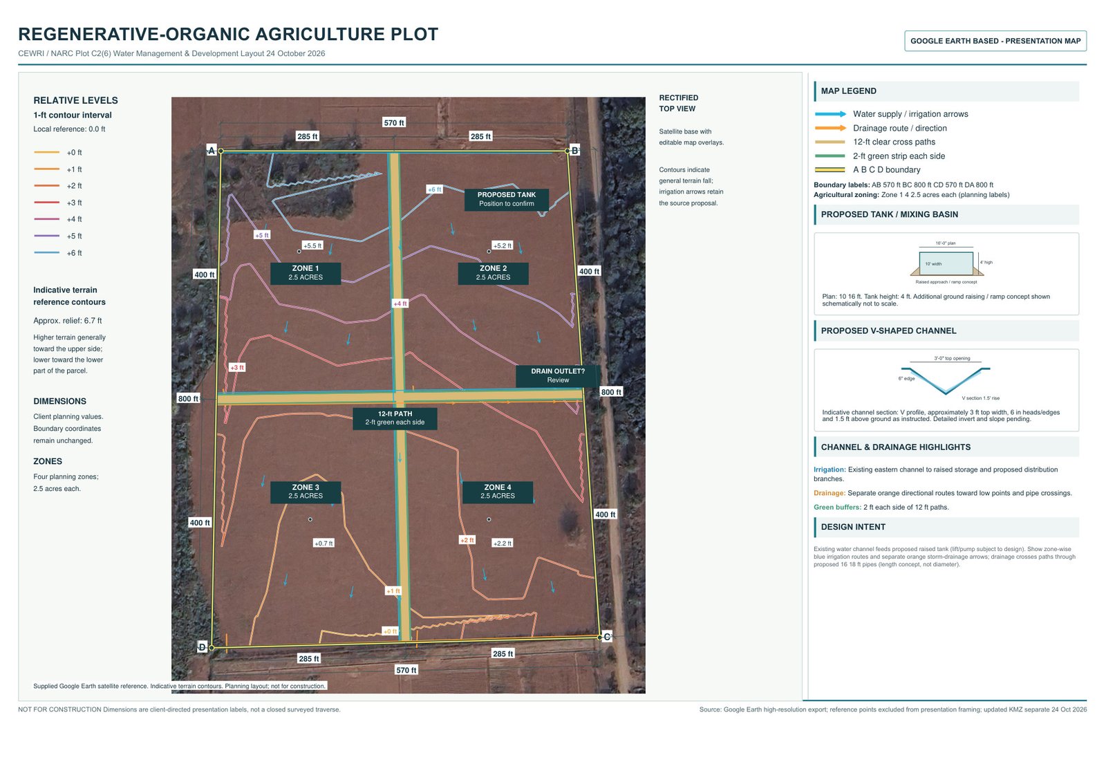
Rev12 CEWRI NARC map with four numbered zones, 1-foot relative contour lines, 570 and 800 foot planning sides, half dimensions and proposed water routes
Supplied Google Earth satellite reference with editable planning overlays. Contours use a 1 ft interval and local relative labels +0 to +6 ft; approximate source relief is 6.7 ft. Blue irrigation and orange drainage arrows retain proposal status and do not prove hydraulic gradients. The existing channel's flow direction remains unconfirmed.

24 October 2026 / Rev12 update

Small relative levels, clear planning decisions.

TERRAIN

1-ft relative contours

Colorful contour lines and selected small level labels show approximate differences from a local zero. The +0 to +6 ft contour labels and about 6.7 ft source relief help explain the general terrain fall. They are modelled references, not verified dumpy-level results; a 1 ft contour interval is not a 1 ft survey-accuracy claim.

LAYOUT

Numbers and dimensions

ZONE 1-4 and 2.5 ACRES use compact two-line labels. Opposite-side planning labels are 570 ft and 800 ft, with 285 ft and 400 ft half divisions. Existing boundary coordinates remain unchanged.

DELIVERY

Static map, editable details

The focused top-view satellite presentation keeps labels, dimensions and contours as real PDF text and vectors. A layered KMZ opens in Google Earth, while the updated project data records the revision, dimensions, terrain basis and outstanding checks.

Method

From survey reference to a workable concept

01 / FIELD REFERENCE

Keep the layout consistent

Rohail's field references and the supplied A–B–C–D coordinates keep planning decisions on one consistent base. Opposite sides are labelled 570 ft and 800 ft in the presentation map; these are planning labels, not a closed cadastral traverse or a claim of legal boundary change.

02 / ACCESS & GREEN SPACE

Make room for movement

The concept reserves 12 ft clear cross paths with 2 ft green or flower strips on each side. The four zones now use only ZONE 1, 2, 3 and 4, with 2.5 ACRES on a second line; crop assignments have been removed. Half-dimension chains show 285 + 285 ft and 400 + 400 ft.

03 / WATER ROUTES

Separate supply from drainage

Blue routes show proposed water distribution. Orange routes show indicative drainage, including proposed pipe crossings at paths toward the existing channel. Direction and outlet levels need field verification.

Design intent

Review the proposed tank, then confirm levels and hydraulics.

A coherent layout first makes the unresolved engineering questions visible.

A proposed raised tank or mixing basin and channel arrangement remains a concept for review against verified source and field levels. The map includes a 10 × 16 ft tank plan with a 4 ft height and a schematic raised approach. A V-shaped channel section is also indicative.

These diagrams communicate intent, not a validated hydraulic design. Pump or lift requirements, channel invert and slope, storage capacity, pipe sizes, connection rights and discharge conditions must be checked before construction.

Delivered outcome: an updated Rev12 planning map with numbered zones, relative terrain contours, dimension chains, a layered Google Earth file and downloadable PDFs for discussion and next-stage design. Construction and performance outcomes are not claimed.
What happens next

Turn the concept into verified design inputs.

  1. Confirm a common vertical datum and surveyed levels at the plot, channel and proposed outlet.
  2. Check source availability, required lift, tank capacity and distribution hydraulics.
  3. Set crossing pipe sizes and drainage grades from measured profiles and outlet conditions.
  4. Review access, permissions and detailed construction drawings before work on site.