
REAL PROJECT / GIS CASE STUDY
Bhon Road, Kallar Kahar: field records to a six-map planning atlas
How field observations, existing client maps and terrain data were brought together for an organised preliminary site review.
Original public atlas: V16 draft · Field visit: 3 October 2026 · Latest report issue: V20, 13 October 2026 · Survey and mapping: Rohail Khalid / Pulse Hatch.
The brief
A hilly site is difficult to understand from one satellite image. The useful questions were where the mapped parcels lie, how the terrain changes, where modeled runoff converges, and how a possible water-transfer connection relates to the terrain. The task was to assemble these questions into an editable GIS project and readable map set.
The output is a planning reference for discussion and follow-up fieldwork. It does not establish legal ownership, a cadastral boundary or a final engineering design.
What the source pack contains
| Item | Recorded in the V16 draft |
|---|---|
| Field records | 59 GPS records retained; 53 grouped as site-associated points |
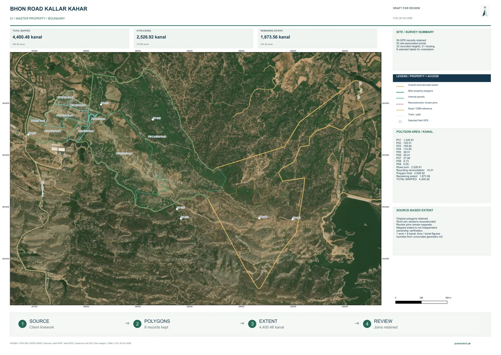
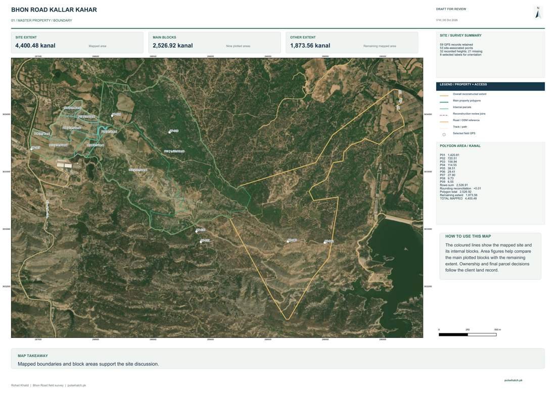
| Mapped extent | 4,400.48 kanal / 550.06 acres, reconstructed from source linework |
| Internal polygons | 9 polygons: 2,526.92 kanal / 315.86 acres |
| Remaining mapped extent | 1,873.56 kanal / 234.20 acres |
| Outputs | 6 thematic map sheets, combined atlas, editable QGIS and Google Earth files |
These areas describe the stored mapped geometry, not independently verified land ownership. Acre and kanal figures were calculated from the same unrounded area and rounded once for display. The project uses 1 acre = 8 kanal.
From field notes to an organised map set
- Keep the source records: original GPS coordinates, reported heights and client reference files were preserved. Travel and approach records were distinguished from the provisional site group.
- Build a common spatial reference: geographic records and source linework were organised for GIS review. The map sheets identify WGS84 / UTM 43N, EPSG:32643.
- Separate questions into themes: property, contours, elevation, slope, drainage and water concept became separate sheets rather than one overloaded map.
- Improve presentation without changing evidence: selected labels, consistent legends, north arrows and scale bars made the maps easier to discuss. Display clipping and colours did not improve source accuracy.
What each map helps the reviewer see
| Sheet | Purpose |
|---|---|
| 01 · Property / boundary | Compare the overall reconstructed extent, internal polygons, access references and selected GPS records. |
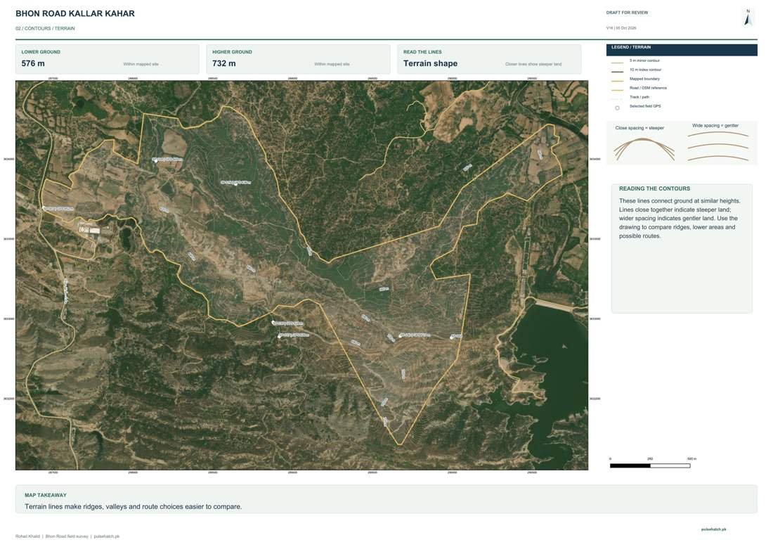
| 02 · Contours / terrain | Read relative relief using 5 m minor contours and 10 m index contours; labels are spaced for readability. |
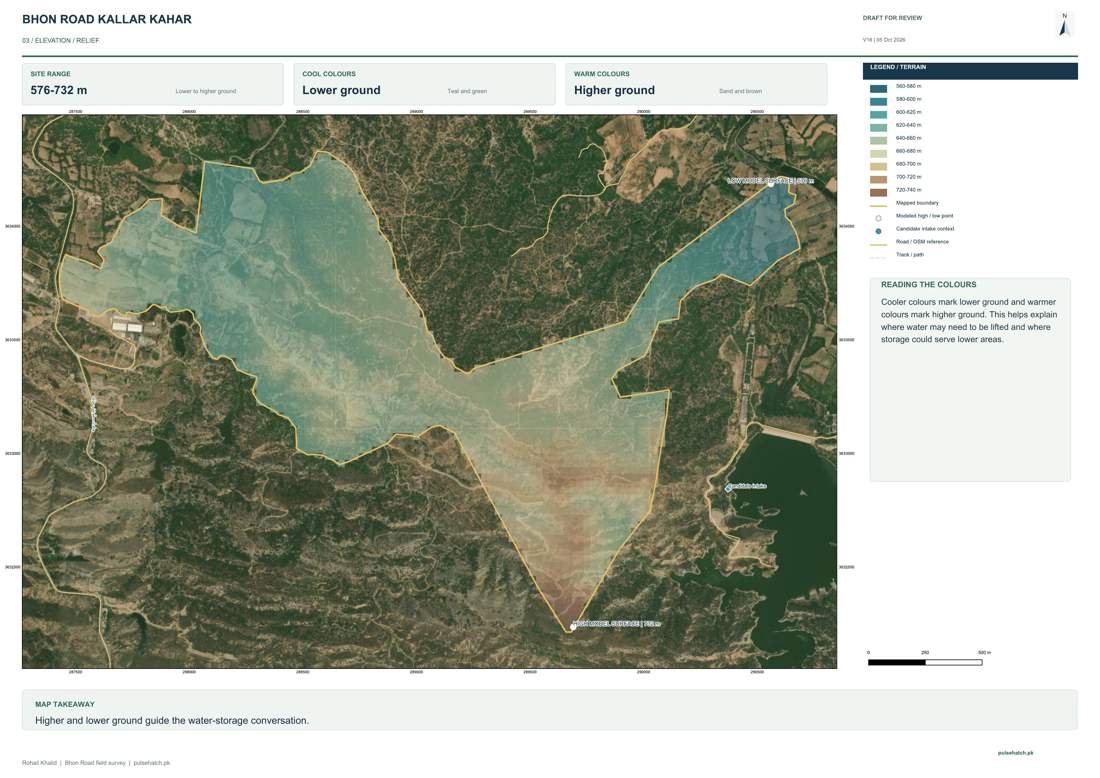
| 03 · Elevation | Compare the modeled surface range of approximately 576–732 m within the mapped boundary. |
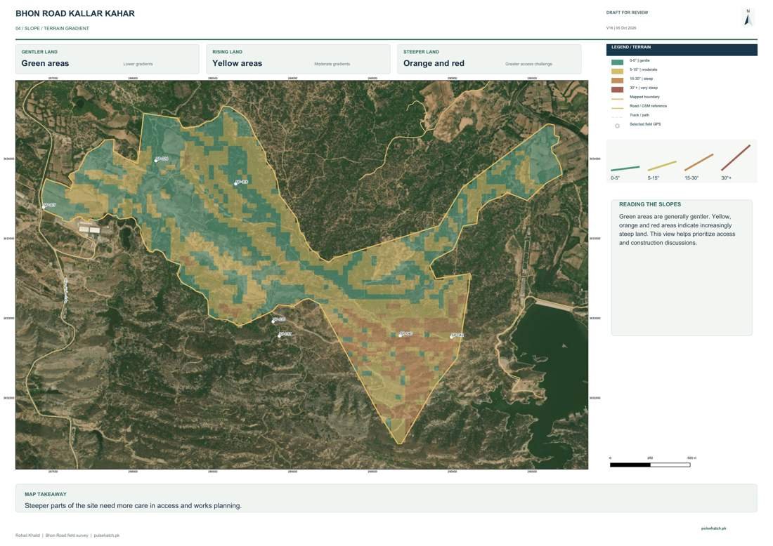
| 04 · Slope | View degree classes of 0–5, 5–15, 15–30 and above 30; these classes are not a development-suitability assessment. |
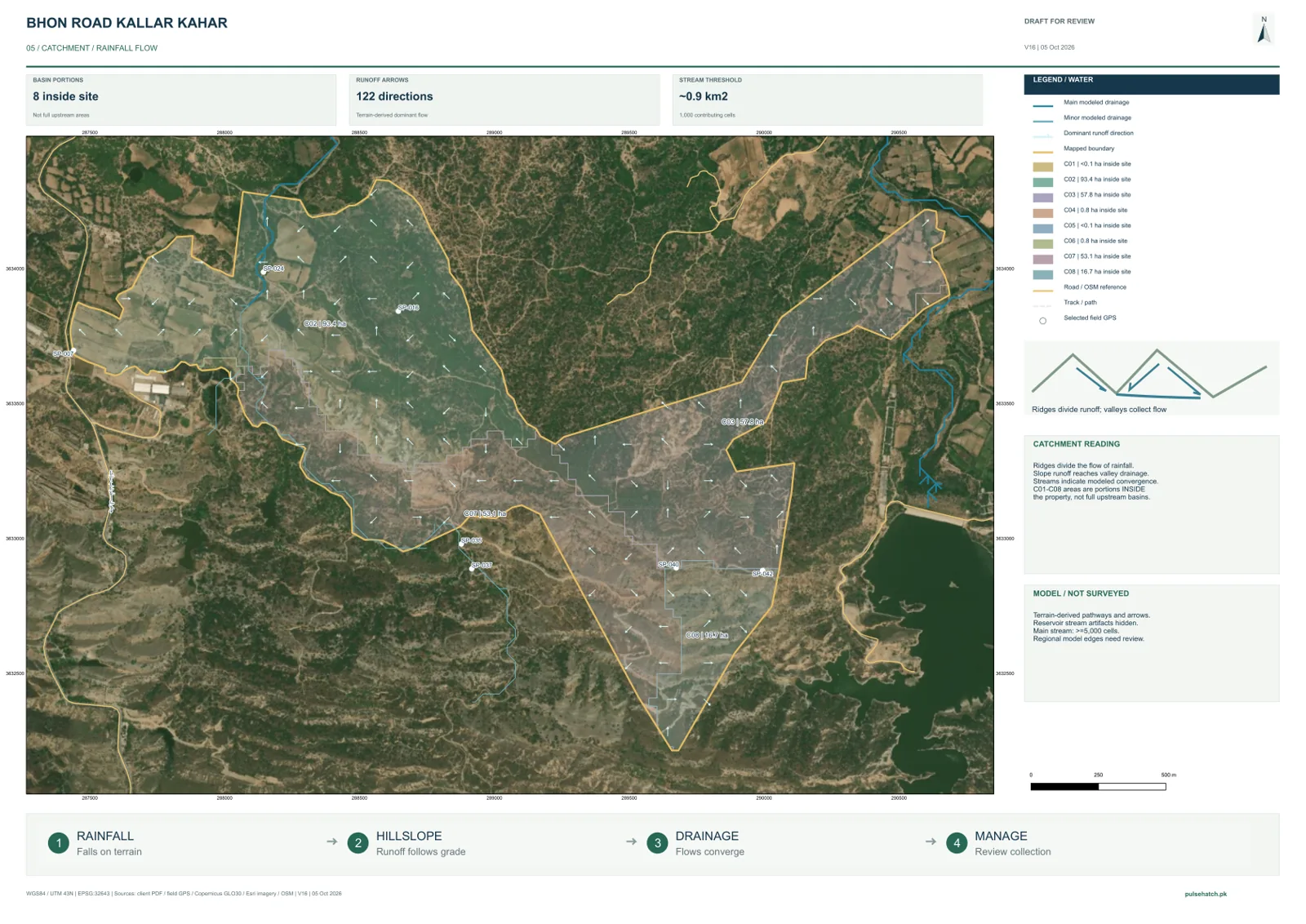
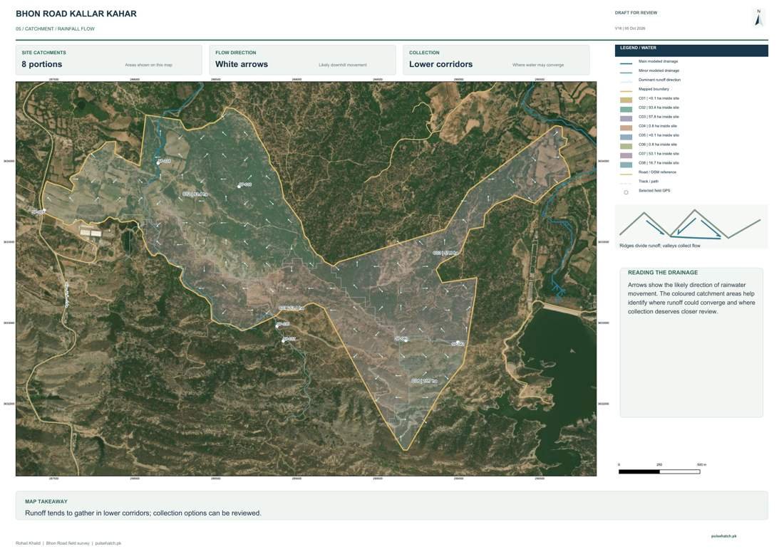
| 05 · Catchment / drainage | Review 8 basin portions inside the mapped extent and 122 terrain-derived flow arrows. |
| 06 · Water concept | Discuss an illustrative connection of about 700 m and a modeled endpoint surface rise of about 90.8 m. Hydraulic design is pending. |

A useful drainage distinction
The drainage sheet shows terrain-derived pathways and catchment portions that fall inside the mapped property. Those portions are different from complete upstream basin areas. The map helps frame questions for site inspection, such as whether channels connect to the expected outlet and whether modeled routes match visible ground features.
The water-transfer sheet is also conceptual. Its modeled surface-height difference is not a measured water level or total pumping head. Water availability, rights, route levels, losses, pipe and pump selection, and storage suitability still need separate verification.
October 2026 update: field survey & site water plan (V20)
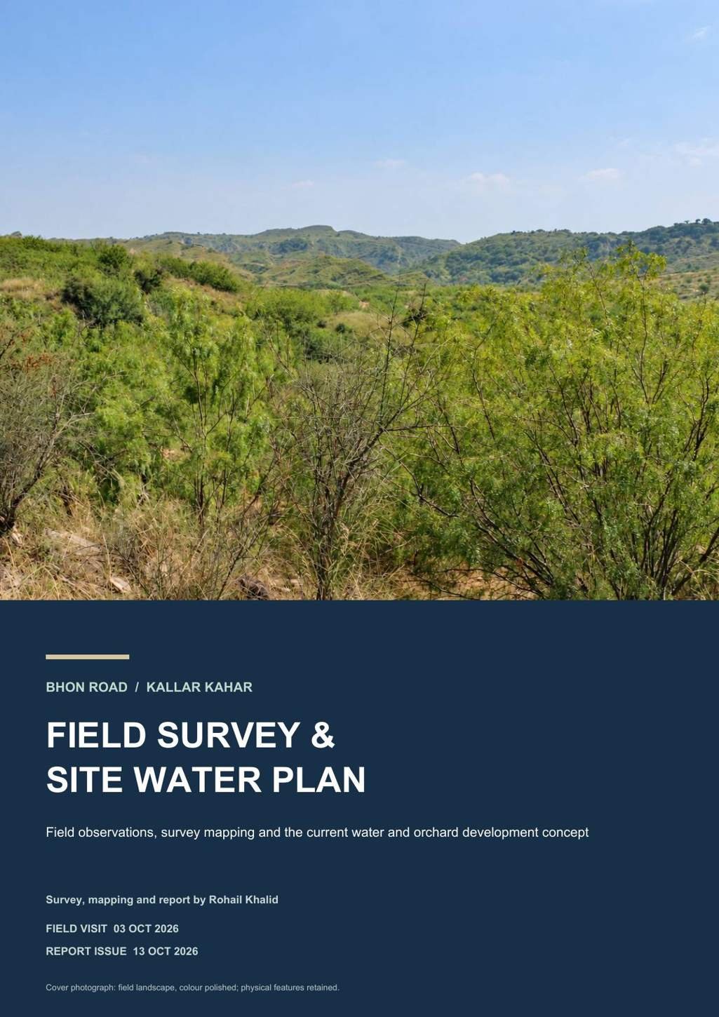
Following the field visit of 3 October 2026, Rohail Khalid prepared an updated 21-page field-survey and site-water planning report, issued 13 October 2026. The original six-map atlas remains a foundation of the work; the later concept develops potential water sources, storage roles, distribution corridors, five management zones and an initial orchard programme. This is a planning discussion, not a final construction design.
Six thematic GIS maps
- Master property: mapped boundaries, nine plotted areas and GPS orientation points.
- Contours & terrain: modeled ground levels and relative relief.
- Elevation: lower and higher surface bands, approximately 576–732 m in the mapped area.
- Slope: gradient classes to inform site access and works planning.
- Drainage: eight terrain-based catchment portions and indicative runoff pathways.
- Water concept: illustrative intake-to-storage route of about 700 m and terrain profile.
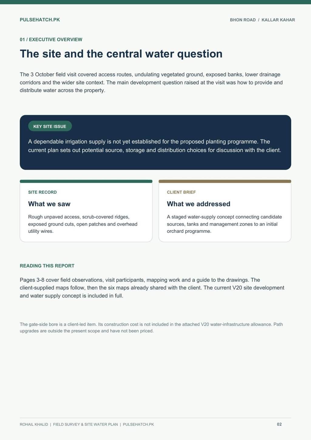
Explore the available public map previews above and below. Source GIS surfaces and early corridors require detailed topographic survey and on-site verification before implementation.
V20 water and orchard planning summary
| Planning item | V20 concept |
|---|---|
| Mapped overall extent | 4,400.48 kanal (reconstructed mapping extent; not legal ownership verification) |
| Water storage | 450 m³ shared main storage planning capacity for the initial planting programme |
| Initial orchard scenario | 410.2 kanal / 51.27 acres, olive-led baseline across five zones |
| Illustrative mature-stage daily water demand | 589.5 m³/day under the stated crop and efficiency assumptions |
| Preliminary initial-phase water-supply allowance | PKR 98.7–154.3 lakh, excluding optional field drip and listed out-of-scope work |
Important scope note: these are concept-level estimates from the client report, not measured source yield, confirmed tank locations, approved hydraulic sizing, verified parcel titles or supplier quotations. Source testing, survey levels, route access, utility clearance and detailed design are still required. The gate-side bore is client-led and was excluded from the stated allowance. Optional drip is separately estimated and must not be added as though included in that water-supply total.
Original field photographs, all GIS maps and V20 report visuals
This is the issued 13 October 2026 client-report artwork reproduced as web-readable pages—not AI-redrawn maps. Tap any image for the large version. GIS legends, source limitations and concept-stage caveats remain visible in the original artwork.
Field survey and site visit — pages 1–8
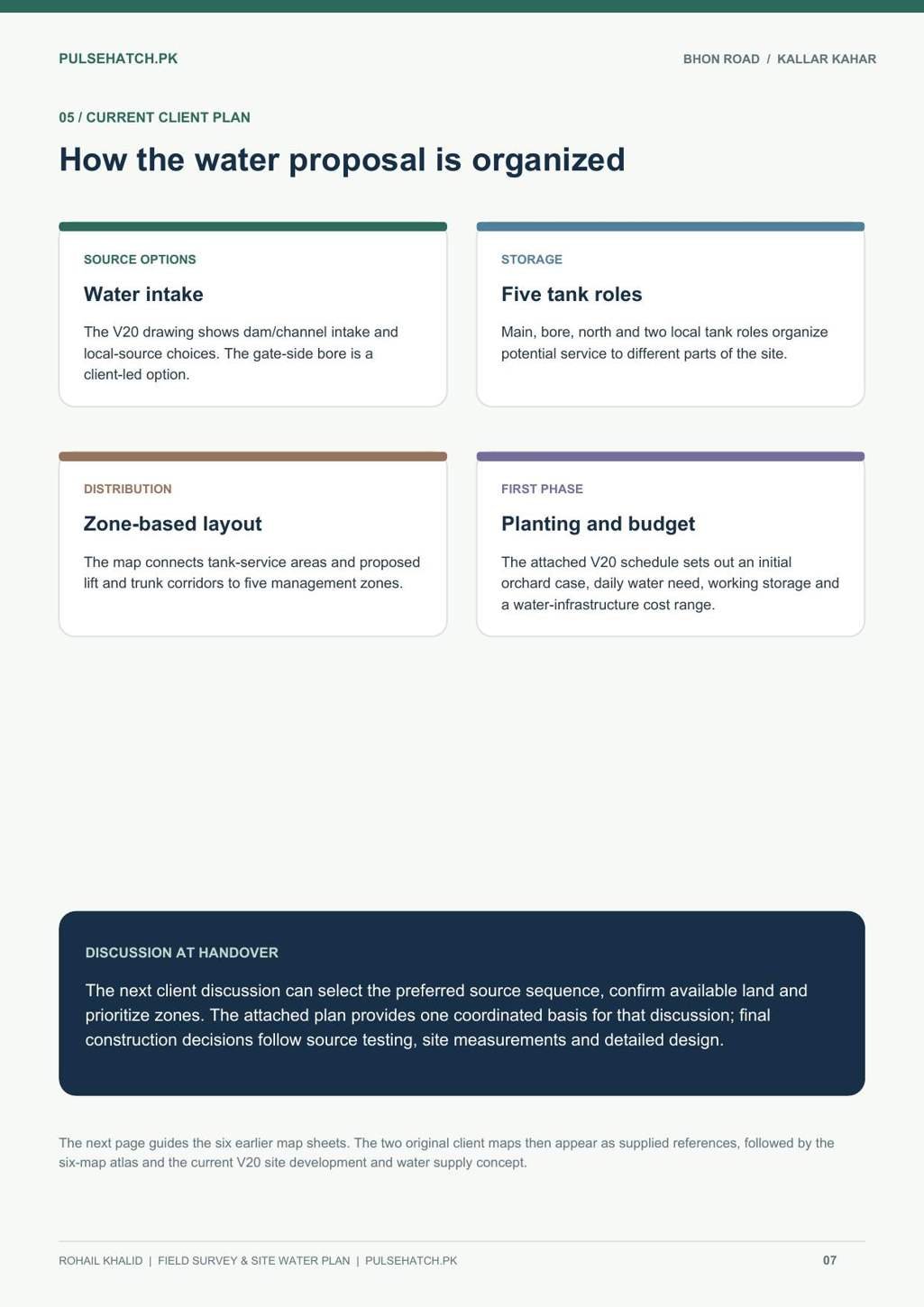
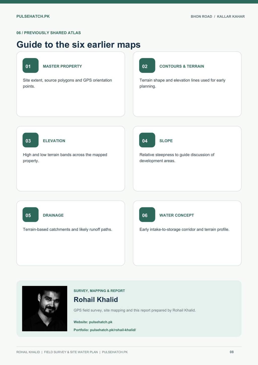
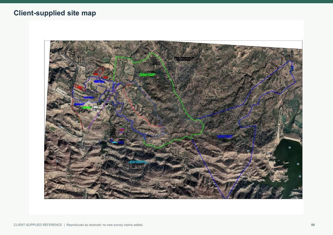
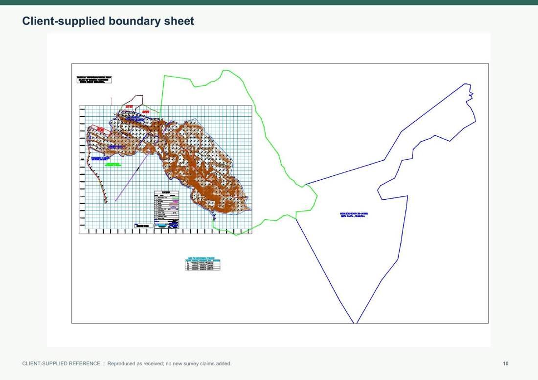
Client references and six thematic GIS maps — pages 9–16

V20 management-zone maps and engineering schedules — pages 17–21
Survey and mapping: Rohail Khalid — Pulse Hatch GIS portfolio. Explore GIS mapping and field survey services, more practical research or request a project consultation.
Full V20 report guide — 21 pages, issued 13 October 2026
The client report is organised as an eight-page field and mapping explanation, two original client-supplied reference drawings, six GIS thematic atlas sheets, and five pages of updated site development and water-supply planning. The website summary below follows that order. The signed-off client PDF itself is not changed or republished here.
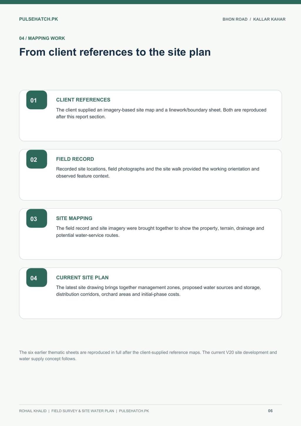
Pages 1–8: field visit, observations and mapping method
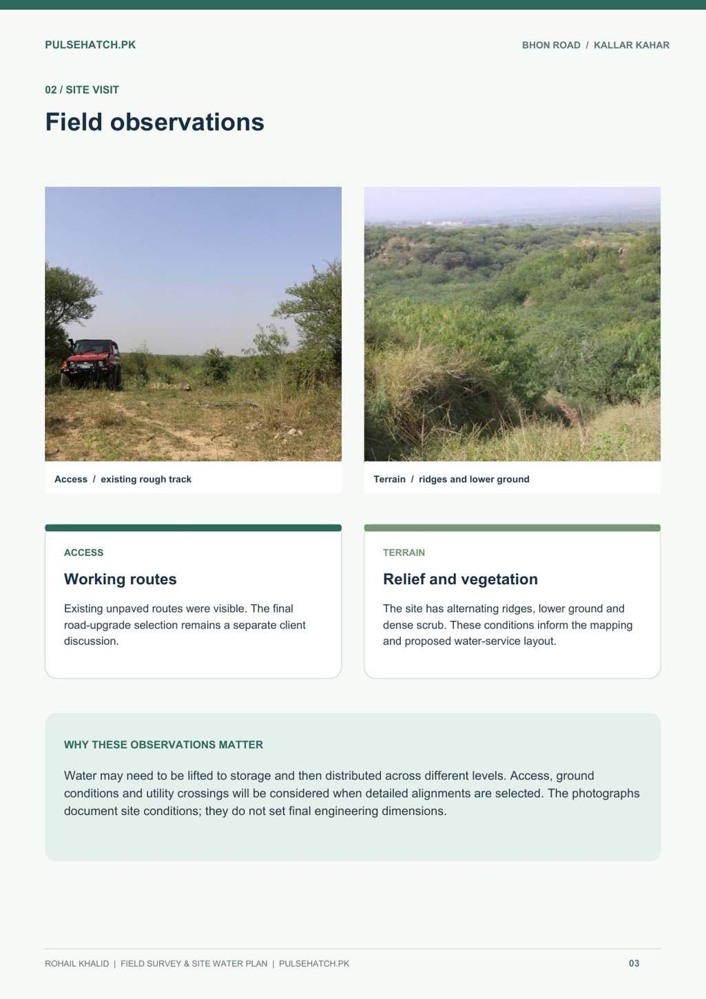
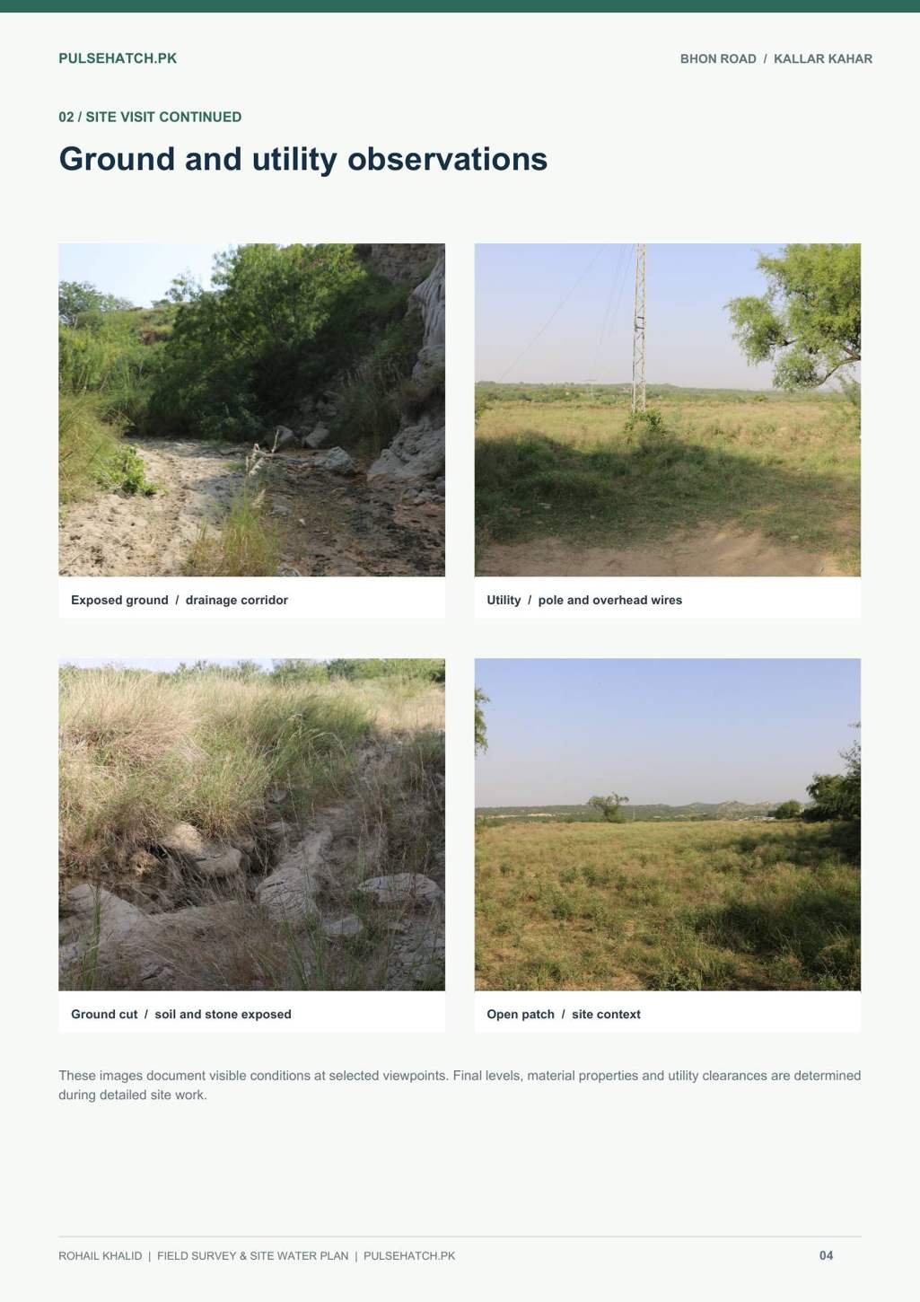
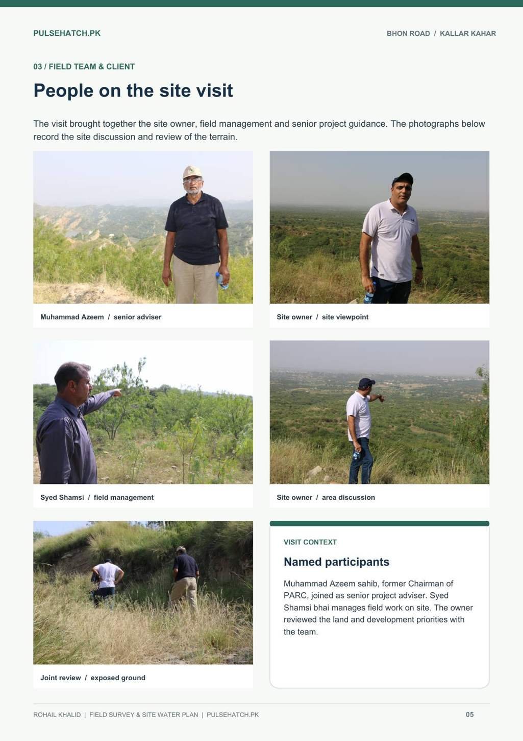
The 3 October 2026 field review recorded rough existing tracks, scrub-covered ridges, lower drainage corridors, exposed cuts, open ground and overhead utility wires. The central client question was how to obtain, store and distribute water across different ground elevations. Field photographs document observations, not measured design levels. Client imagery and boundary references were kept distinct from GPS field observations and later terrain-derived planning layers.
Pages 9–10: original client reference maps
The report preserves the imagery-based site reference and original boundary/linework sheet supplied by the client. These remain attributed client references, not newly verified cadastral or ownership evidence. They are not reproduced separately here.
Pages 11–16: six GIS atlas sheets
| Page / map | Key findings from the issued report |
|---|---|
| 11 — Master property | 4,400.48 kanal mapped extent; nine plotted areas 2,526.92 kanal; remaining mapped extent 1,873.56 kanal. |
| 12 — Contours & terrain | Copernicus 30 m surface; illustrated 5 m contours and 10 m index lines; modeled surface levels 576–732 m. Contour interval is not survey accuracy. |
| 13 — Elevation | Cool colours distinguish modeled lower ground; warm colours show higher bands, supporting discussion of lifts and storage. |
| 14 — Slope | 0–5°, 5–15°, 15–30°, and 30°+ classes illustrate increasing terrain challenge and potential runoff considerations. |
| 15 — Drainage | Eight terrain-based catchment portions with indicative downhill flow arrows; drainage channels require field verification. |
| 16 — Water concept | Early dam-side intake to upper storage illustration, about 700 m route with ground profile; pumping arrangement subject to source testing and detailed hydraulic design. |
Pages 17–18: current site development and water zones
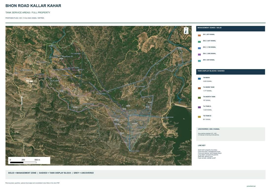
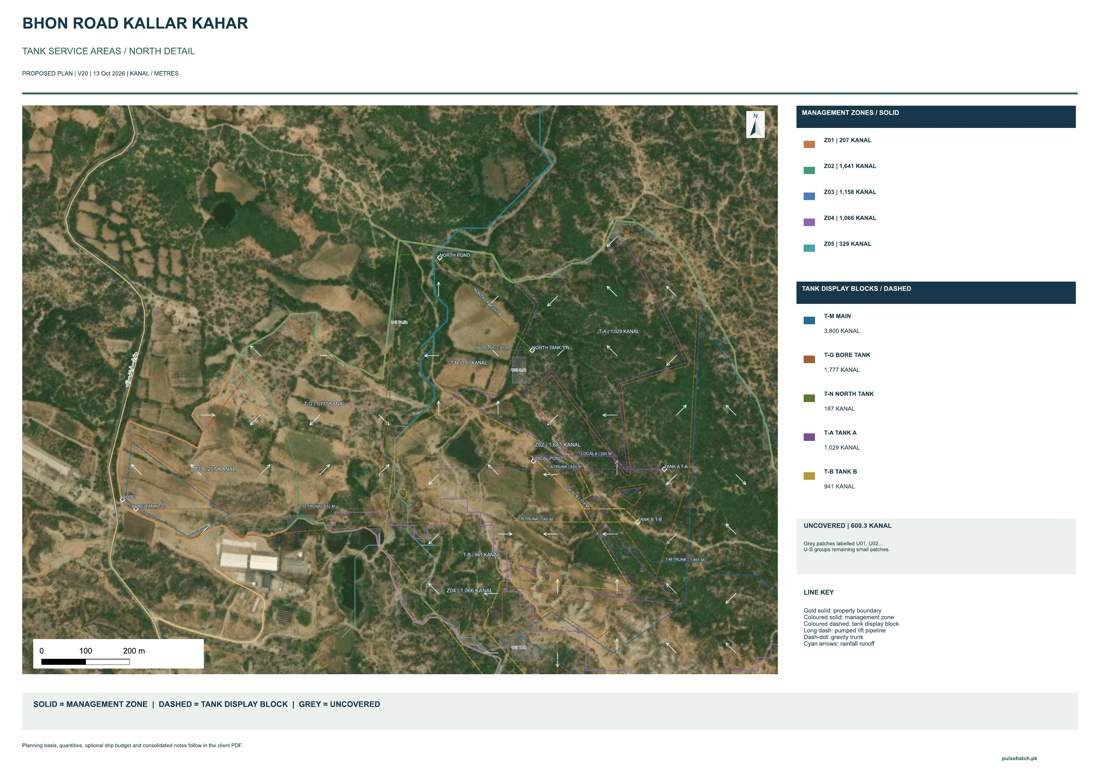
The later V20 plan brings together five management zones, candidate dam/channel or local water-source options, a main storage role, bore-tank role, north tank and two local tank roles. Lift pipelines and gravity trunks are concepts across service areas—not approved surveyed alignments. Service zones may overlap and must not be summed as if they were separate total land holdings.
Page 19: tank service, route schedules and uncovered patches
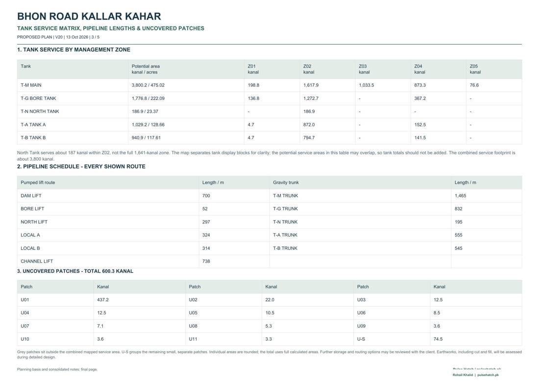
| Lift route | Length | Gravity trunk | Length |
|---|---|---|---|
| Dam lift | 700 m | Main tank trunk | 1,465 m |
| Bore lift | 52 m | Bore tank trunk | 832 m |
| North lift | 297 m | North tank trunk | 195 m |
| Local A | 324 m | Tank A trunk | 555 m |
| Local B | 314 m | Tank B trunk | 545 m |
| Channel lift | 738 m | — | — |
The planning table identifies approximately 3,800 kanal of combined potential service footprint and 600.3 kanal of uncovered patches. Some individual tank-service footprints overlap; the report explicitly warns against adding them together.
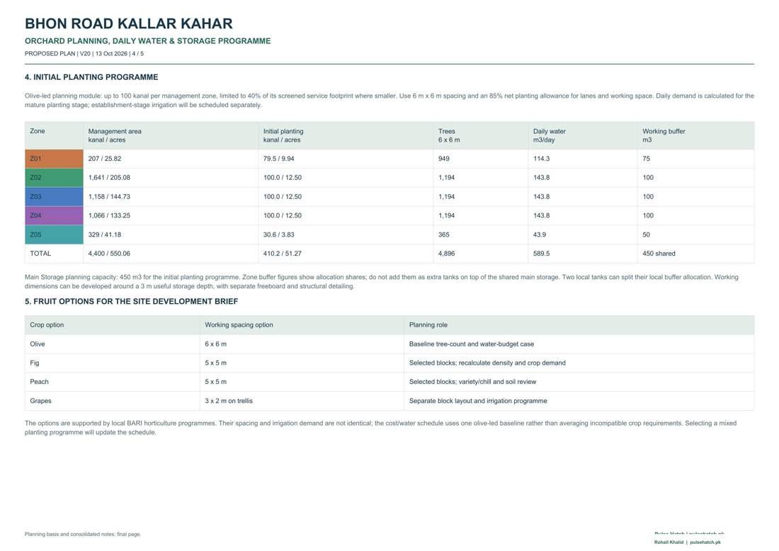
Page 20: initial orchard programme and water demand
| Zone | Initial planting | Olive baseline trees | Daily water |
|---|---|---|---|
| Z01 | 79.5 kanal | 949 | 114.3 m³ |
| Z02 | 100.0 kanal | 1,194 | 143.8 m³ |
| Z03 | 100.0 kanal | 1,194 | 143.8 m³ |
| Z04 | 100.0 kanal | 1,194 | 143.8 m³ |
| Z05 | 30.6 kanal | 365 | 43.9 m³ |
| Total | 410.2 kanal | 4,896 | 589.5 m³/day |
Baseline assumptions: 6 × 6 m spacing, 85% net planting allowance, olive-led mature-stage water estimate, and 450 m³ shared main storage planning capacity. Fig, peach and grape options are considered separately and require their own spacing and irrigation recalculation.
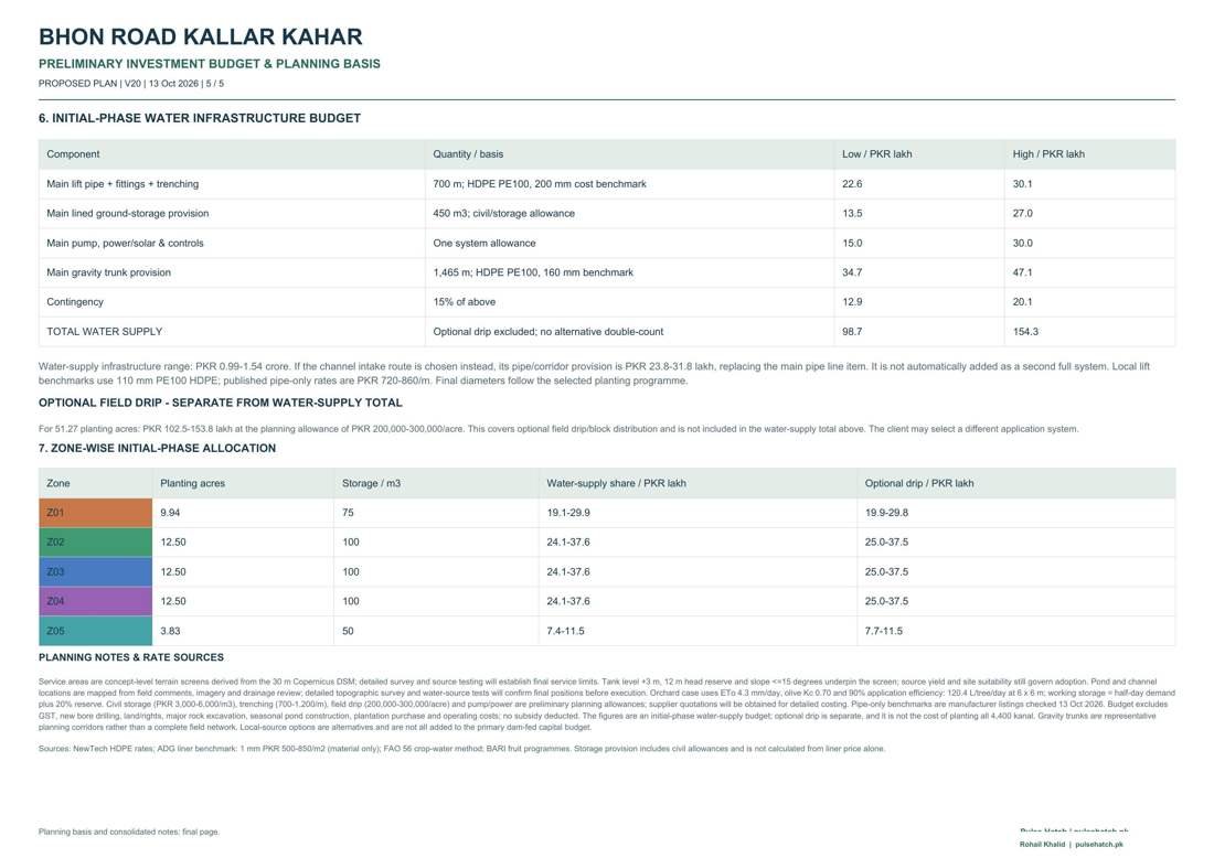
Page 21: preliminary infrastructure budget and limitations
| Component | PKR lakh — low | PKR lakh — high |
|---|---|---|
| Main lift pipe, fittings, trenching | 22.6 | 30.1 |
| Main lined storage provision | 13.5 | 27.0 |
| Pump, power/solar and controls | 15.0 | 30.0 |
| Main gravity trunk provision | 34.7 | 47.1 |
| 15% contingency | 12.9 | 20.1 |
| Water-supply allowance | 98.7 | 154.3 |
The quoted total represents a preliminary water-supply concept of about PKR 0.99–1.54 crore, not full development of all mapped land. Optional field drip on 51.27 acres is separately estimated at PKR 102.5–153.8 lakh; it is excluded from the water-supply total. Gate-side new bore drilling, land/rights, GST, rock excavation, plantation and operating expenses are among the stated exclusions. Pipe rates and quantities must be reconfirmed with suppliers, field levels, route conditions and hydraulic calculations before execution.
Professional interpretation: field records, client-supplied linework and 30 m terrain models support early GIS planning. They do not establish cadastral title, exact source yield, final tank dimensions or construction approval.
Outcome and next steps
The documented result is a six-map review atlas and an editable GIS / Google Earth package. It provides a consistent way to discuss the site and record later corrections. The available draft does not claim construction completion, verified cost savings or a final approved design.
Before detailed design, the next tasks are to confirm parcel scope and boundary records, establish survey control and a vertical datum, measure access and drainage profiles, and check utilities and ground conditions relevant to the proposed work.
Sources and working limits
Prepared from the project field-survey draft, V16 report, V16 Roman Urdu working guide and the 5 October client-draft pack. Public previews reproduce sheets 01, 02 and 05. The source pack retains the original client linework, field GPS, Copernicus GLO30, imagery and OSM credits.
Copernicus GLO30 is a 30 m surface model. Buildings and vegetation can contribute to the represented surface; it is not a replacement for measured ground levels. Read the Copernicus dataset description.
The field report did not establish RTK/DGPS survey accuracy, instrument calibration or an independently confirmed GPS vertical datum. The case study presents the documented workflow and retains these limits.
Have a site that needs a clearer first review?
Send the location, existing maps, the questions you want answered and any field records. Pulse Hatch can review the available material and define an appropriate mapping scope.
Discuss a mapping project Rohail Khalid’s portfolio